Blog
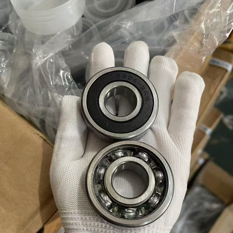
What Is a Bearing Tolerance
Bearing Tolerance Definition:
Bearing tolerance refers to the allowable limits of variation in the dimensions and geometry of a bearing. These tolerances are set by international standards and determine how much the actual size, shape, and fit of a bearing can differ from its specified measurements.
Tolerances are important because they affect how the bearing fits on the shaft and in the housing, as well as how it performs in terms of speed, load capacity, and lifespan. Bearings with tighter (more precise) tolerances are used in high-precision applications, such as machine tools or aerospace equipment, while standard tolerances are suitable for general industrial use.
Tolearance Tables:
Standard tolerances (P0) for radial bearings, excluding tapered roller bearings
| Inner ring | ||||||||||||
| d | tΔdmp1) | tVdsp1) | tVdmp | tΔBs | tVBs | tKia | ||||||
| Diameter series | All | Normal | Modified3) | |||||||||
| > | ≤ | U | L | 7, 8, 92) | 0, 1 | 2, 3, 4 | U | L | L | |||
| mm | μm | μm | μm | μm | μm | μm | ||||||
| – | 2.5 | 0 | –8 | 10 | 8 | 6 | 6 | 0 | –40 | – | 12 | 10 |
| 2.5 | 10 | 0 | –8 | 10 | 8 | 6 | 6 | 0 | –120 | –250 | 15 | 10 |
| 10 | 18 | 0 | –8 | 10 | 8 | 6 | 6 | 0 | –120 | –250 | 20 | 10 |
| 18 | 30 | 0 | –10 | 13 | 10 | 8 | 8 | 0 | –120 | –250 | 20 | 13 |
| 30 | 50 | 0 | –12 | 15 | 12 | 9 | 9 | 0 | –120 | –250 | 20 | 15 |
| 50 | 80 | 0 | –15 | 19 | 19 | 11 | 11 | 0 | –150 | –380 | 25 | 20 |
| 80 | 120 | 0 | –20 | 25 | 25 | 15 | 15 | 0 | –200 | –380 | 25 | 25 |
| 120 | 180 | 0 | –25 | 31 | 31 | 19 | 19 | 0 | –250 | –500 | 30 | 30 |
| 180 | 250 | 0 | –30 | 38 | 38 | 23 | 23 | 0 | –300 | –500 | 30 | 40 |
| 250 | 315 | 0 | –35 | 44 | 44 | 26 | 26 | 0 | –350 | –500 | 35 | 50 |
| 315 | 400 | 0 | –40 | 50 | 50 | 30 | 30 | 0 | –400 | –630 | 40 | 60 |
| 400 | 500 | 0 | –45 | 56 | 56 | 34 | 34 | 0 | –450 | – | 50 | 65 |
| 500 | 630 | 0 | –50 | 63 | 63 | 38 | 38 | 0 | –500 | – | 60 | 70 |
| 630 | 800 | 0 | –75 | – | – | – | – | 0 | –750 | – | 70 | 80 |
| 800 | 1 000 | 0 | –100 | – | – | – | – | 0 | –1 000 | – | 80 | 90 |
| 1 000 | 1 250 | 0 | –125 | – | – | – | – | 0 | –1 250 | – | 100 | 100 |
| 1 250 | 1 600 | 0 | –160 | – | – | – | – | 0 | –1 600 | – | 120 | 120 |
| 1 600 | 2 000 | 0 | –200 | – | – | – | – | 0 | –2 000 | – | 140 | 140 |
| Outer ring | ||||||||||
| D | tΔDmp | tVDsp4) | tVDmp4) | tΔCs | tKea | |||||
| Open bearings | Capped bearings5) | tVCs | ||||||||
| Diameter series | ||||||||||
| > | ≤ | U | L | 7, 8, 92) | 0, 1 | 2, 3, 4 | 2, 3, 4 | |||
| mm | μm | μm | μm | μm | μm | |||||
| 2.5 | 18 | 0 | –8 | 10 | 8 | 6 | 10 | 6 | Identical to tΔBs and tVBs of an inner ring of the same bearing | 15 |
| 18 | 30 | 0 | –9 | 12 | 9 | 7 | 12 | 7 | 15 | |
| 30 | 50 | 0 | –11 | 14 | 11 | 8 | 16 | 8 | 20 | |
| 50 | 80 | 0 | –13 | 16 | 13 | 10 | 20 | 10 | 25 | |
| 80 | 120 | 0 | –15 | 19 | 19 | 11 | 26 | 11 | 35 | |
| 120 | 150 | 0 | –18 | 23 | 23 | 14 | 30 | 14 | 40 | |
| 150 | 180 | 0 | –25 | 31 | 31 | 19 | 38 | 19 | 45 | |
| 180 | 250 | 0 | –30 | 38 | 38 | 23 | – | 23 | 50 | |
| 250 | 315 | 0 | –35 | 44 | 44 | 26 | – | 26 | 60 | |
| 315 | 400 | 0 | –40 | 50 | 50 | 30 | – | 30 | 70 | |
| 400 | 500 | 0 | –45 | 56 | 56 | 34 | – | 34 | 80 | |
| 500 | 630 | 0 | –50 | 63 | 63 | 38 | – | 38 | 100 | |
| 630 | 800 | 0 | –75 | 94 | 94 | 55 | – | 55 | 120 | |
| 800 | 1 000 | 0 | –100 | 125 | 125 | 75 | – | 75 | 140 | |
| 1 000 | 1 250 | 0 | –125 | – | – | – | – | – | 160 | |
| 1 250 | 1 600 | 0 | –160 | – | – | – | – | – | 190 | |
| 1 600 | 2 000 | 0 | –200 | – | – | – | – | – | 220 | |
| 2 000 | 2 500 | 0 | –250 | – | – | – | – | – | 250 | |
P6 class tolerances for radial bearings, excluding tapered roller bearings
| Inner ring | ||||||||||||
| d | tΔdmp1) | tVdsp1) | tVdmp | tΔBs | tVBs | tKia | ||||||
| Diameter series | All | Normal | Modified3) | |||||||||
| > | ≤ | U | L | 7, 8, 92) | 0, 1 | 2, 3, 4 | U | L | L | |||
| mm | μm | μm | μm | μm | μm | μm | ||||||
| – | 2,5 | 0 | –7 | 9 | 7 | 5 | 5 | 0 | –40 | – | 12 | 5 |
| 2,5 | 10 | 0 | –7 | 9 | 7 | 5 | 5 | 0 | –120 | –250 | 15 | 6 |
| 10 | 18 | 0 | –7 | 9 | 7 | 5 | 5 | 0 | –120 | –250 | 20 | 7 |
| 18 | 30 | 0 | –8 | 10 | 8 | 6 | 6 | 0 | –120 | –250 | 20 | 8 |
| 30 | 50 | 0 | –10 | 13 | 10 | 8 | 8 | 0 | –120 | –250 | 20 | 10 |
| 50 | 80 | 0 | –12 | 15 | 15 | 9 | 9 | 0 | –150 | –380 | 25 | 10 |
| 80 | 120 | 0 | –15 | 19 | 19 | 11 | 11 | 0 | –200 | –380 | 25 | 13 |
| 120 | 180 | 0 | –18 | 23 | 23 | 14 | 14 | 0 | –250 | –500 | 30 | 18 |
| 180 | 250 | 0 | –22 | 28 | 28 | 17 | 17 | 0 | –300 | –500 | 30 | 20 |
| 250 | 315 | 0 | –25 | 31 | 31 | 19 | 19 | 0 | –350 | –500 | 35 | 25 |
| 315 | 400 | 0 | –30 | 38 | 38 | 23 | 23 | 0 | –400 | –630 | 40 | 30 |
| 400 | 500 | 0 | –35 | 44 | 44 | 26 | 26 | 0 | –450 | – | 45 | 35 |
| 500 | 630 | 0 | –40 | 50 | 50 | 30 | 30 | 0 | –500 | – | 50 | 40 |
| 630 | 800 | 0 | –50 | – | – | – | – | 0 | –750 | – | 60 | 45 |
| 800 | 1 000 | 0 | –60 | – | – | – | – | 0 | –1 000 | – | 60 | 50 |
| 1 000 | 1 250 | 0 | –75 | – | – | – | – | 0 | –1 250 | – | 70 | 60 |
| 1 250 | 1 600 | 0 | –90 | – | – | – | – | 0 | –1 600 | – | 70 | 70 |
| 1 600 | 2 000 | 0 | –115 | – | – | – | – | 0 | –2 000 | – | 80 | 80 |
| Outer ring | ||||||||||
| D | tΔDmp | tVDsp4) | tVDmp4) | tΔCs | tKea | |||||
| Open bearings | Capped bearings5) | tVCs | ||||||||
| Diameter series | ||||||||||
| > | ≤ | U | L | 7, 8, 92) | 0, 1 | 2, 3, 4 | 0, 1, 2, 3, 4 | |||
| mm | μm | μm | μm | μm | μm | |||||
| 2,5 | 18 | 0 | –7 | 9 | 7 | 5 | 9 | 5 | Identical to | 8 |
| 18 | 30 | 0 | –8 | 10 | 8 | 6 | 10 | 6 | tΔBs and tVBs | 9 |
| 30 | 50 | 0 | –9 | 11 | 9 | 7 | 13 | 7 | of an inner ring | 10 |
| of the same | ||||||||||
| 50 | 80 | 0 | –11 | 14 | 11 | 8 | 16 | 8 | bearing | 13 |
| 80 | 120 | 0 | –13 | 16 | 16 | 10 | 20 | 10 | 18 | |
| 120 | 150 | 0 | –15 | 19 | 19 | 11 | 25 | 11 | 20 | |
| 150 | 180 | 0 | –18 | 23 | 23 | 14 | 30 | 14 | 23 | |
| 180 | 250 | 0 | –20 | 25 | 25 | 15 | – | 15 | 25 | |
| 250 | 315 | 0 | –25 | 31 | 31 | 19 | – | 19 | 30 | |
| 315 | 400 | 0 | –28 | 35 | 35 | 21 | – | 21 | 35 | |
| 400 | 500 | 0 | –33 | 41 | 41 | 25 | – | 25 | 40 | |
| 500 | 630 | 0 | –38 | 48 | 48 | 29 | – | 29 | 50 | |
| 630 | 800 | 0 | –45 | 56 | 56 | 34 | – | 34 | 60 | |
| 800 | 1 000 | 0 | –60 | 75 | 75 | 45 | – | 45 | 75 | |
| 1 000 | 1 250 | 0 | –75 | – | – | – | – | – | 85 | |
| 1 250 | 1 600 | 0 | –90 | – | – | – | – | – | 100 | |
| 1 600 | 2 000 | 0 | –115 | – | – | – | – | – | 100 | |
| 2 000 | 2 500 | 0 | –135 | – | – | – | – | – | ||
The Relationship Between Bearing Tolerance and Limit Dimensions:
As mentioned above, bearing dimensional tolerance refers to the permissible variation in the actual size of a bearing from its nominal (design) size. Limit dimensions, on the other hand, are the maximum and minimum allowable dimensions that a bearing can have according to specified standards.
The relationship between them is that the tolerance defines the range within which the actual bearing size must fall, while the limit dimensions specify the exact upper and lower boundaries of this range. In other words, the tolerance is the difference between the maximum and minimum limit dimensions. Adhering to these tolerances and limit dimensions ensures that bearings fit and function properly in their applications.
Why Bearing Dimensions Matter?
Bearings are high-precision components that require strict adherence to dimensional specifications. If the dimensions deviate beyond acceptable limits, several issues can arise:
Excessive Clearance: This can reduce operational accuracy and cause vibration.
Overly Tight Fit: This increases friction, which may lead to overheating or even bearing seizure.
Accelerated Wear: Dimensional inaccuracies can shorten the bearing’s service life.
Installation Challenges: Improper dimensions make assembly more difficult, impacting both efficiency and cost.
Therefore, understanding bearing dimensional tolerances and limit dimensions is crucial for both buyers and engineers.
Questions buyers still ask while reviewing What Is a Bearing Tolerance
Which next options usually help after reviewing What Is a Bearing Tolerance?
Most buyers benefit from one broader family destination, one more commercial route, and one supporting guide that answers the next practical question. That combination usually turns research into a clearer shortlist.
Why add related bearing destinations beside What Is a Bearing Tolerance?
Because the first answer often leads to a second question about fit, applications, supplier choice, or repeat-order confidence. Keeping those next destinations close reduces unnecessary backtracking.
When is it worth moving from reading into a quote or product review?
That move usually makes sense once the topic has narrowed the likely bearing family and the remaining unknowns are commercial, dimensional, or application-specific rather than purely educational.
What usually makes the next bearing decision easier after What Is a Bearing Tolerance?
The process is often easier when the wider family view, the more commercial destination, and one practical guide stay visible together. That keeps the decision grounded in both application detail and buying reality.
Buyer FAQ
Questions buyers ask before choosing the next bearing option
What is the main takeaway from What Is a Bearing Tolerance?
The main takeaway is that what is a bearing tolerance should be checked against the bearing family, dimensions, load direction, speed, and operating conditions instead of relying on the title or size alone.
When should I use this guide before requesting a quote?
Use the guide when you are comparing bearing models, checking suffix meanings, confirming seal or clearance choices, planning maintenance, or preparing details for replacement, production, or OEM sourcing.
How does this topic connect to bearing supply?
The topic supports the Bearing Supply decision path by helping buyers understand fit, performance, specification details, or maintenance factors before choosing a product page or contacting the team.
Can this guide replace a final specification check?
No. The guide helps prepare the decision, but a final check should still confirm the part number, dimensions, load, speed, seal, clearance, precision, application, and order quantity.
What should I send if I need help after reading this guide?
Send the bearing number, measured size, photos if available, application, quantity, and any special operating conditions. That gives the team enough context to recommend the right product family or quote route.
Need help checking fit, price, or lead time? Request a bearing quote


